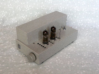
6N6P Class-A Differencial PP Amp

.jpg

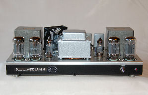
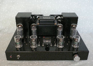
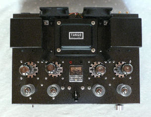
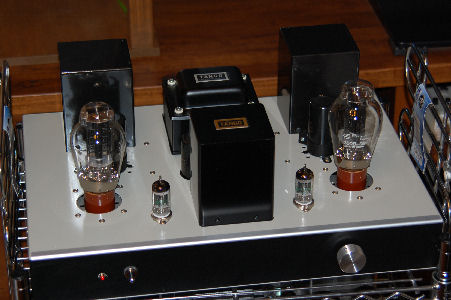
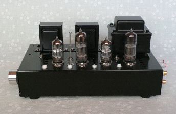
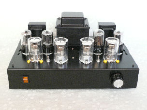
Well known among tube amp builders in Japna? 6N6P amplifier designed and parts prepared to be distributed by Mr. Perche.
The photo is a model revised with a new power transformer.
The amp is stable even after years of using.

-1/3-
.jpg

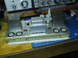
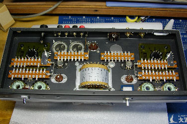
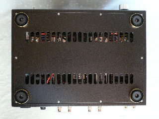
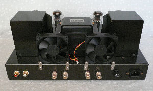
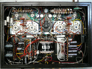
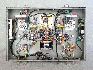
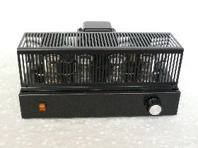
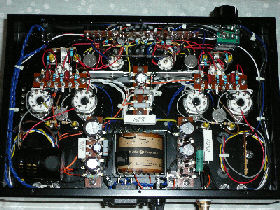
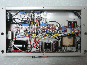
I replaced usual wire with shielded one to the input circuit as I changed power transformers.
A big capacitor is added to the power circuit to enhans the lower sound.
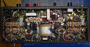
MISTAKES:The building was the work I did after many many years. That is, I didn't follow the way I ought to in the building process. I overlooked a few wrong wirings and broke a pilot LED lamp and a resistor as I put on the power for the first time. Other than thise, there were two more wrong wirings.

-2/3-
Postscript
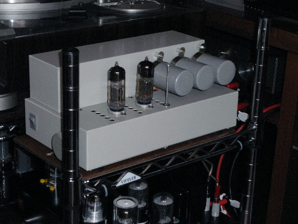
I learned that when wiring, you should trace with a red pencil the finished wiring line on the circuit diagram! The amp underwent two big reformations. It is now used as my main amp in the living room. See condenser tuning of tube amps.

-3/3-

Return to the list
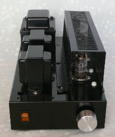


16LU8 Class-A Defferencial PP Amp

16lu8.jpg

My second(next to 6N6P Perche amp) class-A differential push-pull amplifier built on a LUXMAN KMQ60 chassis. Specs:
Driver tube: 6FQ7
Output tube: 16LU8
OPT: Tango FE-25-5
PT: PMC-190SH

-1/5-

16LU8 m.jpg

Parts mounted on chassis
LUXMAN KMQ60 was a kit with 50CA10s for output tubes. I built it when I was in my twenties. It has been kept(left not touched) in a storage for decades.

-2/5-

16LU8 m.jpg

Inside chassis ready for wiring.
First I wanted to restore it but one of the output transformers had been broken, and 50CA10 had a poor reputation. On top of it, I was much interested in building differential amplifiers.
Thus I built the amp as shown in the title.

-3/5-

16LU8 m.jpg

Wiring was hard for the chassis was not deep enough because a larger number of parts than those of the original. Also, I had to used original holes for fitting parts and they made some wiring longer than needed.

-4/5-

postscript
The sound of the amp was satisfactry but unfortunately the amp suffered hum.
The cause of hum was the wrong ground points. However, the troubleshooting was difficult as I haven't clear understanding of 'how to ground.'
I could successfully kill hum after many tries and errors. I learned 'how to ground properly.' The volume, which is fitted on the back panel, is a trace of the hum killing measures.

-5/5-

Return to the list


6DJ8+6DJ8+6CA7 Class-A Defferencial PP Amp

Preface Skip Preface
Somehow I was bound by high output power without reason when I built this amplifier. I picked up KT88s for final tubes and asked, as usual, Mr. H to design an over 10 watts output power audio amplifier.
He designed 6FQ7+6FQ7+KT88 amp and each of us built one for one's own. Mr. H completed first and we had a trial listening. During the trial, he plugged in 6AC7s in place of KT88s. I found 6AC7 makes a better sound and I decided to adopt 6CA7s for my amp on the spot.
I asked him to modify the circuit to make the amp a dedicated one for 6AC7s. I spent a few more days to complete re-wiringit and that way I had my own 6AC7 amp. I still have four brand-new KT88s.
I added my original device to the amp. That is, I installed a small center meter (see the photo below) in order to check the current balance between the plates of tubes.
I wanted to make this amp a special one in my life. So, I spent as much time as was needed. Likewise, I accepted any troubles to make it a good one.
About one year after I had completed the amp, I found 6DJ8 is much better than 6FQ7. Naturally, I modified the circuit again and replaced 6FQ7s with 6DJ8s.
It took more than a year to finalize the amp. The building started with designing the chassis and finished with installing polycarbonate covers to 6DJ8s. The covers keep the tubes warmer and, as I found after my experiment, contribute to stabilize their operation.

-1/7-

6ca7 m.jpg

Front view
In adjusting current between tubes, first you set the rotally switch so as to the right corresponding adjusting volume is selected. Then you adjust the volume for the current of pair tubes to be balanced.
OPT: Softon RX-40-5
PT: Tango MX-280

-2/7-

.jpg

Back panel of the chassis
The chassis was made to order at N Technology.
I drew the plan by CAD, which was new to me, and it took some time to complete it.
Thanks to the advice given by Mr. H, I learned how to use CAD and it is now my indispensable tool.

-3/7-

.jpg

Back view
Two fans cool down four 6CA7s. The tubes, in total, dissipate about 100-watt heat. The fans are driven with lower voltage in order to lower the noise.

-4/7-

.jpg

Inside view of the chassis
The wiring was modified two times. The modification was done carefully and neatly each time so as not to cause any future trouble.

-5/7-

.jpg

Top view This was the main amplifier of our house until 2014 when the 6AH4 amp was completed.

-6/7-

postscript
Mistakes I made:
There were one mal-soldering and two wrong wirings.
The mal-soldering was found at one of the input terminals. The appearance was good but the hot side was not conductive. Mr. H found it after I left his house. Big thanks to him!

-7/7-

Return to the list


5687 + 300B Single Amp

300b m.jpg

I built this amp intrigued by the well reputed name of 300B.
I obtained 300Bs from a HAM friend, Mr. L. He bought a few set of 300Bs as he visited China on business. The amp was built to the design by Mr. H, another HAM friend of mine, too.
Specifications:
Driver tube:5687
OPT:Softon RW-20
Choke:Tango LC-10-200D
Chassis:Made to order Designed by Mr. H
The shassis is designed larger for the sake of building practice.

-1/3-

.jpg

Heater current of 300B is supplied by two DC switching power supply units.
Each power supply is mounted on the side wall inside the chassis.

-2/3-

Postscript

The sound, which is most important, is a little thin compared to push-pull amps.
A 71A amp, which is also a sigle amp, makes as rich sound as that of push-pull amps. Is 71A exceptional?
On top of the thin sound, the amplifier isn't perfectly free of hum. You can hear it as you bring your ear close to a woofer.
The source of hum seems to be the ripples slightly existing on DC power supply. The hum trouble is left unimproved as I judged the amp not worth improved with its poor sound.

-3/3-

Return to the list
  

32A8→6GW8→6DJ8+6N6P Class-A Differencial PP Amp

.jpg

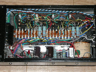
After building the 6N6P amplifier, I wanted one with more output power.
Mr. H responded to me and we both built a 32A8 amplifier each with made to order power transformers.
To my dissappointment, the sound of the 32A8 amps was not good. It was rough.
I rewired and replaced 32A8s with 6GW8s. The sound became smoother but it wasn't as goog as that of the 6N6P amp yet.

-1/6-

.jpg

I rewired it again into a 6DJ8+6N6P amplifier.
However, perhaps due to repeated rewiring, the amp became very unstable.
The ZDs to control the currents in plate circuits were prone to thermal runaway. On top of it, the plate current seemed to have been designed not enough for stable operation of 6DJ8s.

-2/6-

.jpg

I took the following two measures to improve the operation.
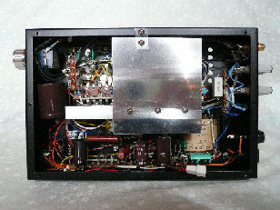
1. I installed a heatsink and a fan as you see them in the photos.
2. I asked Mr. H to modify the circuit to increase the plate current of 6DJ8s.

-3/6-

.jpg

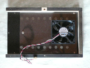
I set the fan in a new wooden frame to be attached between the bottom cover and the amp chassis, choking all the unnecessary holes with a piece of plastic sheet. The fan was picked up among the calm ones.
The photo shows the fan in the frame.

-4/6-

.jpg

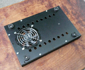
The photo shows the outer side of the bottom cover.
The measures worked. Besides, the fan worked well and I obtained an all season small tube amplifier.

-5/6-

Postscript
I learned some important things through the modifications to an amp that was once finished. A modification causes troubles that can't be identified.
Fortunately, I could suppress the trouble in this case forcibly.
I built another amp with the same tubes and parts and it had been free of troubles.

-6/6-

Return to the list


6DJ8+6N6P Class-A Differencial PP Amp On Perche Chassis

.jpg

Photo: Side view of the amp
Once I set my audio equipment into a mult-amp system when I built this amp for squawkers and tweeters using my 6CA7 amp for woofers. It is my conclusion that 6DJ8+6N6P is the best combination of tubes for a mall output power amplifier.

-1/4-

.jpg

In building a new amp, how or from where you get the chassis is always a big problem. This time I had memory that I read the Perche chassis for mini watters is capable of mounting four tubes.
I checked that the chassis is sold with two tube mounting holes in the front side area leaving the same area size in the rear side.
I bought one and, as you see in the photo, punched two more holes to mount four tubes in line. The chassis was re painted in black.

-2/4-

.jpg

Photo: Inside the chassis
The amp was built on the same circuit diagram as the former 6DJ8+6N6P amp which was converted from 32A8 amp.
I made a hole on the chassis over where ZDs are fitted inside the chassis in order to let the warmer air flows out. I installed heatsinks for ripple filter FETs and plate current regulating FETs independently, too.

-3/4-

Postscript
I could finish building this amp very smoothly and it has been woking smooth, too. The only point not good is that the shassis is not stout.
I could build this amp making good use of what I had learned through my past amp buildings. Besides, I had got used to wiring too, and it looks neet, isn't it?

-4/4-

Return to the list


6DJ8+6DJ8+6AH4 Cass-A Differencial PP Amp

Preface-1 (skip preface)
My amp building started with a 6N6P amp, a mini-watter and it escalated to building more powerful ones. That is, 6AH4 amp didn't catch my eye at first because it wasn't powerful.
As I built one after another, I began to notice why Mr. Perche picked up that 6AH4 amp in Passionate Tube Amplifier. The reason was the quality of the sound and not the power which I wanted with a 6CA7 amp. However, I wasn't so sure yet about the fact until I listened to the sound of the 6AH4 amp which Mr. H built. It wasn't a warming up model for beginners. It was one of the last tube amps for those who want to listen to music in good sound.

-1/7-

Preface-2
The output power of my 6CA7 amp is about 12 watts whereas that of my 6AH4 amp is about 4. I had had a wrong notion about power that 4 watts are not enough. The truth is, 4 is enogh for listening to music in an ordinery room in an ordinery Japanese house. The VU meters I have, which are set to show 2 watts at 100% scale, prove it. The needle only moves up to far below 1 watt scale even when the sound was very, very loud.
Like the former amps I built, I asked Mr. H to modify the original circuit that uses FET+6FQ7+(6AH4x2) into the one with 6DJ8+6DJ8+(6AH4x2), for I like the sound of 6DJ8. The curret between plates of 6DJ8s is a bit unstable and I have to balance it regulerly but I accept the nuisance for the good sound of the tubes.
This amp has been the main amp of our home ever since it was built.

-2/7-

.jpg

PTs are made to order. OPTs are convensional(?) KA-8-54Ps. The output power is a little less than 4 watts/channel at 5% distortion.
As I have written above, the output power is enough for my music listening in our 8-tatami-mat room.

-3/7-

.jpg

To improve the unstable operation of 6DJ8s, I covered them to keep them wormer with jackets made from a poly carbonate pipe.
This had been my main amp until 6N6P amp took the place when it was condenser tuned.

-4/7-

.jpg

Mr. F, a friend of ours who also built tube amps, didn't like naked amps and ordered covers and gave me one. The cover is good especially when cleaning.

-5/7-

.jpg

Inside of chassis
ZDs are fitted in the place where air flows and they don't get heated.
When I built this amp, I had been skilled in wiring and I could finish it neatly.
Things end when you get the skill. My amp building seems to be coming to an end. I built exceptional last one(71A single amp) after this.

-6/7-

Postscript
I stopped using 6CA7 amp after I had completed this amp, which I expected to be my lifelong amp and devoted my energies. The former one is on the same rack but only used when to compare the sound.
The sound of 6AH4 amp is more graceful and tender with the touch of velvet, which 6VA7 amp can never match.
I learned that building a good amp is possible with ordinery not expensive parts. On top of it, I could outgrew that groundless notion that the powerful output is neede for good hi-fi music.
Thanks to Mr. Perch and Mr. H.

-7の7-

Return to the list


71A Single Amp

71a m.jpg

My last amplifier
When I built the 6AH4 amp, I was satisfied wiht its sound and thought it'd be the last amp I build. However, when I heard the sound of 71A amp's at Mr. H's, it overthrew my notion that a single amp can never beat a push-pull amp in sound. My desire for building an 71A tube amp was kindled.
Specifications
TUBES:(12AX7+71A)/channel
PO:Made to order for 71A-SRPP
OPT:Toei Trans Formers T-1200
TUBES:12AX7+71A CHASSIS:Made to order. Thanks to Mr. F

-1/3-

71a wiring m.jpg

Inside of the chassis
It may be natural but the inside of the chassis is so sparse. More sparse than that of 6N6P amp.
The output power is about 0.3 watts. Mr. H's 71A amp has about 0.6watts with a KA-7530 OPT

-2/3-

Postscript
As I stated on the page of 300B, this single amp is an exceptional single amp with its ample lower sound.
The quality of the sound is very good being similar to that of 6AH4 differential p-p amp.
Although the power is small, with its volume turned to full in my study, it disturbs my son in the next room and makes him say it's too loud!
Each time I listen I'm lost in the music that comes out from this amp. It is connected to one of my BUHS speaker systems.

-3/3-

Return to the list
   

A Digital Amp Driven by 6DJ8s

d-amp completed.jpg

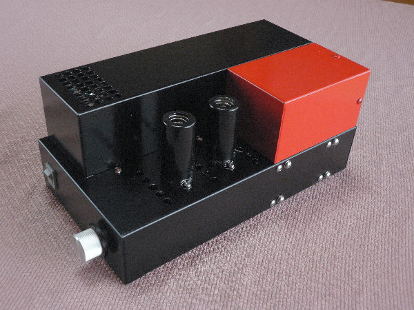
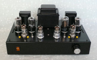
I bought a set of parts for the 6DJ8s pre-amp from Mr. Perche with which to build a hybrid audio power amp using a module with a Tripath TA2020-020, which hereafter is cited as D-amp. I bought the module at the web store run by Kyohritsu Electronic Industry Co., Ltd.
I mounted all the parts and components on a mini-watter shassis which I was afraid will most likely be consequent only to build a noise amplifier. Luckily, however, the sound from the amp was clear!

―1/8―

d-amp naked.jpg

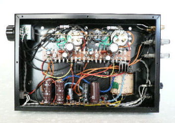
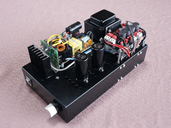
The photo is the amp made naked without covers.
The unit in front of the power transformer is a switching power supply for DC 16V-4.2A.
In front of the power unit is a regulator for DC 12V-5A.
On the right side of the transformer is the digital power amp unit.

―2/8―

ready to be painted.jpg

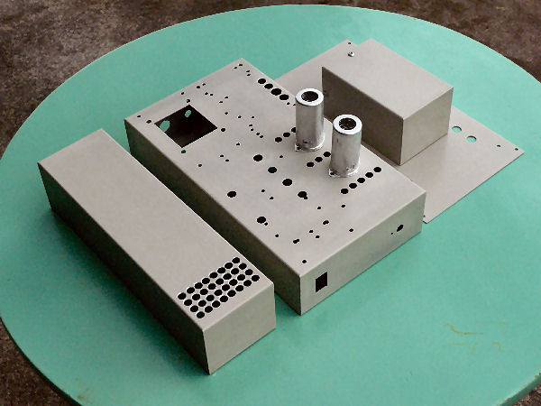
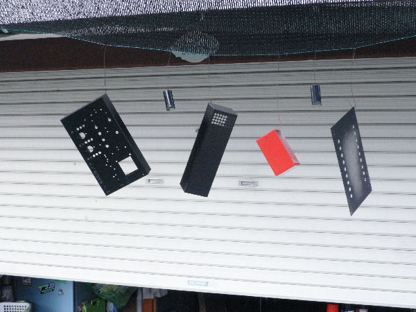
The photo shows the shassis, the covers and the tube cases ready to be painted.
The shassis became full of holes. Designing the shassis I was careful for any hole not to become inaccessible behind other parts or componets. However one hole turned out to be inaccessible.
The smaller box is made with the same long cover I had bought before and kept. Last time I used the shassis only and didn't use the cover. I was successful in cutting the cover with a saw for steel.

―3/8―

chassis painting.jpg

The photo shows how I let those painted objects dry.

―4/8―

d-amp bed.jpg

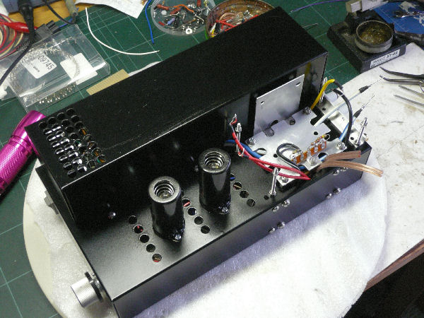
The photo shows a process of building. The vertical aluminum plate is a heat sink for the D-amp.
The horizontal aluminum plate is attached after a trial of the amp for the pop noise canceller I bought with the D-amp turned out useless. I planned to make it a preparatory rack for a small print board, on which I assumed to assemble a pop noise suppressing circuit.
In the end, I only attached on it an L-shaped terminal as my applied circuit of the transitional voltage suppressor developed by Mr. Perche worked perfect.

―5/8―

chassis inside wiring.jpg

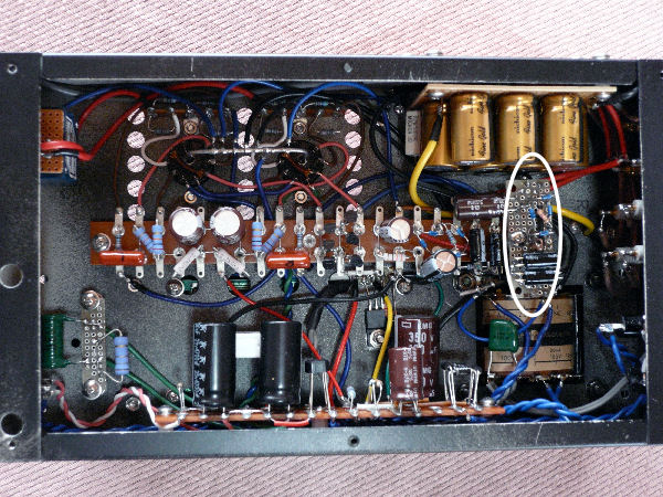
The photo shows the inside of the shassis. At the upper right are the stacked condensers for the D-amp.
The white oval shows the transitional voltage suppressor I built the circuit of which is condensedly installed on a 1/2 of d-sized print board.

―6/8―

sleep on-off circuit.jpg

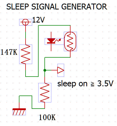
The chart is a circuit that provides with sleep signal for D-amp. The original circuit which I applied here is devised by Mr. Perche. Refer to his web site for details.
I installed two couplers preparing for needed cases but one was enough.
The destructive on-off noises on speakers were perfectly evaded with this device. Big thanks to Mr. Perche!

―7/8―

Postscript
The amp sounds as good as other amps I have built, no better though. I installed a tube pre-amp in order to avoide insipid sounds and it perhaps worked.
Mr. Perche's articles suggest us to be very careful in building a pre-amp as it easily become a noise amplifier. There wasn't any guarantee that I can build one free of such noises from transformer induction, a switching power supply and modulation noises of D-amp. I should say I was lucky. The amp seems free of such noises, at least, to my ears. The latter two noises are above our hearing range too.

―8/8―

Return to the list